| Q: |
Installation of the AMD Athlon and Duron CPU (AN7, KD7A, KV7, KV7-V, KW7, NF7, NF7-M, NF7-S, NF7-S2, NF7-S2G, VA-10, VA-20) |
| A: |
NOTE |
- Installing a heatsink and cooling fan is necessary for heat to dissipate from your processor. Failing to install these items may result in overheating and processor damage.
- The AMD Socket A processor will produce a lot of heat while operating, so you need to use a large heat sink that is especially designed for the AMD socket A processor. Otherwise, it may result in overheating and processor damage.
- If your processor fan and its power cable are not installed properly, never plug the ATX power cable into the motherboard. This can prevent possible processor damage.
- Please refer to your processor installation manual or other documentation with your processor for detailed installation instructions.
|
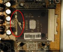
The AMD Socket A Athlon and Duron processor installation is easy, like Socket 7 Pentium processors before. Because it uses the "Socket A" ZIF (Zero Insertion Force) socket, you can easily fix the processor firmly into position. Figure 2-3 shows you what the socket A looks like, and how to open the lever. The socket A has more pins than the socket 7. Therefore, a Pentium level processor cannot be inserted into a socket A.
 |
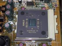
When you raise the lever, you have to loosen the socket lock. Please raise the lever to the end, and prepare to insert the processor. Next, you need to align the processor pin 1 to the socket pin 1. If you put it in the wrong direction, you will not be able to insert the processor easily, and processor pins will not fully go into the socket. If this is the case, please change the direction, until it easily and fully inserts into the socket A. See Figure 2-4. At the same time check the processor temperature detection thermistor height (if your motherboard has this component), then you can slowly insert the processor into the Scoket A. Finally, you need to check that the processor edge and the Socket A edge is parallel. It should be parallel and not tilted.
When you finish the above, push the lever down to its original position, you should feel the lever lock the socket A. You have then finished the processor installation.
Heatsink Installation Hints
Please follow the sequence metioned below, Do Not inverse the sequence. Otherwise, you may have a situation like the photo on the left. Because of the design of the CPU socket, the left side hooks are not as strong as the right side hooks. If you follow our suggestions you will prevent your processor and socket from damage.
 |
Please follow the sequence metioned below, Do Not inverse the sequence. Otherwise, you may have a situation like the photo on the left. Because of the design of the CPU socket, the left side hooks are not as strong as the right side hooks. If you follow our suggestions you will prevent your processor and socket from damage. |
|
NOTE |
| Considering the chassis structure problem, please always take off the motherboard from chassis, before adding or removing a heatsink kit. |
The proper procedure to install the heatsink kit:
 |
First, install the processor into the processor socket.
|
 |
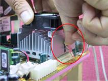
Insert the heatsink left side fix plate into the processor socket left side fix hooks. Make sure the fit is very tight. Check the photo on the left. |
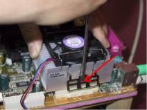 |
Insert a flat screwdriver into the middle slot of the right side fix plate and push down. Then you can push the fix plate over the socket hooks on the right side. Check the photo on the left. |
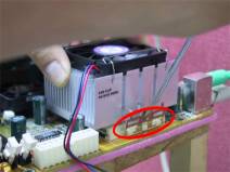 |
Check the photo on the left. You have finished the heatsink installation.
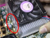
Now hold the whole heatsink and slightly shake it, make sure the buttom right side of the heaksink does not contact the right side of the Socket (see bottom picture). Otherwise, the processor die does not have proper contact with the heatsink. This situation may cause processor damage.
Remember to install the heatsink fan power cable to the CPU fan header on the motherboard.
Now you can reinstall the motherboard back into the chassis.
When all above procedures done, you can connect the ATX power cable to the motherboard.
|
 |
* If you have different types of heatsink kit, please refer to the manual that came with the heatsink kit. The left photo shows another type of heatsink fix plate design. The install sequences are still the same, from right side to left side. Just remember that.
We strongly recommand you to buy a heatsink with three holes in the fix plate. This will provide the best stabability and won¡¦t cause the Socket fix hooks to be broken or damaged. |
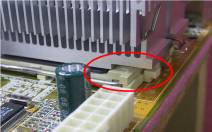 |
* The left photo shows the bottom right side of the heaksink in contact with the right side of the Socket. In this situation, the processor die does not properly contact the heatsink. If you start the computer at this monent, it will immediately cause the processor damage. Always check this place when you finish the heatsink installation. |
|